
Decrement delay & Thermal buffering - 80
Anyone familiar with spending a hot summer's day in a caravan and then another in a stone house with closed shutters will appreciate the meaning of ‘Decrement delay’. The inside of the caravan closely maps the rise and fall in external temperature to provide the familiar stifling effect on the occupants. In contrast, the internal air temperature of the stone house stays well below the midday heat, barely varies throughout the day and so provides relative comfort to those sheltering from the sun.

In the caravan, as soon as the outside cladding starts to heat up, output is detected within minutes on the inside face as most of the heat quickly transfers through the aluminium / lightweight insulation composite; whereas as the face of the stone wall heats up, the heat is absorbed by the stone and progresses slowly from the outside inwards. Hours later, some of that heat has arrived on the inside face of the wall whilst the remainder is released back into the cooler evening air.
The interesting, and often baffling, aspect of this phenomena is that the two materials can have very similar u-values - so that in steady-state conditions where heat applied at a constant rate over a period of time to the external face of both materials, there is an equally constant flow of (diminished) heat from the inside surfaces. Crucially though, for the purposes of thermal design, one material will start delivering heat to the inside before the other.
Heat transfer factors: Conductivity, Density and Specific Heat Capacity
But lets start with understanding how different materials cause different heat flow rates. What’s actually happening within the materials? The answer relates to the dynamics acting between three variable characteristics whose values are unique to each material. The rate of heat transfer is determined by:
Specific heat capacity
Specific heat capacity is the important factor in slowing-up the transfer of heat. It is defined as the amount of heat required to raise the temperature of 1kg of a material by one degree Centigrade.
Density
The density refers to the mass (or 'weight') per unit volume of a material and is measured in kg/m3. A high density material maximises the overall weight and is an aspect of 'low' thermal diffusivity.
Thermal conductivity/ λ (lambda) - value
Thermal conductivity measures the ease with which heat can travel through a material. For 'low' thermal diffusivity, 'low' conductivity is an essential part of the equation.
And of course a further factor is the quantity, or thickness of material the heat is transferred through.
Thermal Diffusivity
Thermal Diffusivity ties the above factors together into an equation that measures the ability of a material to conduct thermal energy relative to its ability to store thermal energy. In effect it is a measure of thermal inertia or ‘buffering’.
The equation is:
Thermal diffusivity = thermal conductivity / specific heat capacity x density
Examples:
Rigid polyurethane insulation has a thermal diffusivity of approximately 4.46 x 10⁻⁷ m2/s
Timber fibre insulation has a thermal diffusivity of approximately 1.07 x 10⁻⁷ m2/s
Copper has a thermal diffusivity of around 1.11 × 10⁻⁴ m2/s
In a material with high thermal diffusivity, heat moves rapidly through it because the substance conducts heat quickly relative to its volumetric heat capacity or 'thermal bulk'.
In the above three examples we can see that heat races through copper while it moves more rapidly through rigid polyurethane than it does through timber fibre board.
Introducing the variable heat source - Periodic heat flow
‘Thermal diffusivity’ then accounts for the different rates of heat transfer through the variety of materials from a constant heat source.
However, when we look at the transference of the heat from the sun striking real-world roofs and walls, the heat source is not constant. The variability caused by such as the sun’s passage through the sky is known as ‘periodic heat flow’ and, because the sun behaves in the same way every day (‘diurnal’), its effects can be designed for.
Decrement delay
So, what is ‘Decrement delay’ and what can it do for us? In discussing its use we’re looking to take advantage of the fact that some materials are slower at transferring heat than others. In buildings, the benefits of decrement delay are only realised where the outside temperature fluctuates significantly higher and lower than the inside temperature. So, ideally, if the maximum heat delivery to the wall or roof is at around midday, and because we can achieve a delay in heat transfer, it should be possible for that heat to finally penetrate the wall or roof to the interior of the building some time later when the inside of the building is relatively cool and the outside temperature has fallen as the sun goes down. At this point the heat ‘stored’ in the wall can be released from the wall in both directions without overheating the inside.
The time it takes the peak temperature in the middle of the day on the outside of a wall or roof, to make its way to a peak temperature on the inside face, is called 'time lag' or, more commonly, 'Decrement delay'.
By controlling decrement delay it is possible to control and prevent the overheating of a building.
A delay of between 8 and 12 hours might be considered optimum.
(It’s worth noting too at this point that in a construction element containing several layers, the sequence of the material layers that heat passes through is also a factor in determining decrement delay. For example, in masonry construction where insulation forms one layer, locating it on the exterior of the masonry can significantly enhance the decrement delay effect.)
How Decrement delay / Thermal buffering works on a rendered stone wall

Amplitude damping and the ‘Decrement factor’
A stable indoor temperature is an aspect of thermal comfort. In conditions where the outside temperature fluctuates relatively widely, a constant indoor temperature is desirable. For example an outside temperature might vary between 10ºC and 30ºC while internally it might vary just 1º above or below 20ºC. The fabric of the building envelope has effectively dampened the degree of oscillation.

The ability to attenuate the amplitude of the outside temperature to that of the inside is known as the 'decrement factor'.
It is calculated as f (the decrement factor) = Ti (the maximum swing from the ambient temperature on the inside) / Te (the swing in external temperature)
Example: From above, the peak to peak amplitude of the outside temperature is 20 degrees, and for the inside temperature it is 4 degrees.
f = Ti / Te = 1 / 10 = 0.1
Hence the closer the decrement factor approaches zero, the greater the effect the construction element has on attenuation. Ie the smaller the decrement factor, the more effective the wall / roof at suppressing temperature swings.
The decrement factor is determined by the type and thickness of the materials that make up the wall or roof that the heat passes through.
(Confusingly, the same effect or 'amplitude suppression' is often expressed as a straight ratio. Taking the example above, the ratio would be 10:1 or 5:1 or more often just '10') Construction element containing several layers, the sequence of the material layers that heat passes through is a factor in determining decrement delay. For example, in masonry construction where insulation forms one layer, locating it on the exterior of the masonry can significantly enhance the decrement delay effect.
Calculating decrement delay
The response of construction elements to periodic cycles in temperature and heat gain can be quantified by using the thermal admittance framework as described in EN ISO 13786:2007. The framework also provides the basis for the CIBSE 'Simple Dynamic Model' for calculating cooling loads and summertime space temperatures (CIBSE (2005) Guide A: Environmental design).
Manually calculating thermal response simulations is not for the faint hearted, but a number of programs are available to take the load - notably the freely available, Excel spreadsheet based 'Dynamic Thermal Properties Calculator' developed by Arups and distributed by the Concrete Centre. (www.concretecentre.com/online_services/design_tools/thermal_calculator.aspx )
The importance of decrement delay
Decrement delay will nearly always be more important in hotter climes than in the UK. An exception though, is in timber / steel frame construction. One of the more common criticisms directed at lightweight construction is the lack of thermal mass - which can lead to the familiar 'caravan effect' above. Whereas masonry construction has the obvious benefit of 'heavy' materials such as brick and block, framed structures are typified by combinations of cavity and lightweight insulation - leading to low thermal diffusivity and so little in the way of decrement delay.

(Above) - Wood fibre insulation boards (Pavatex) used on a pitched roof. Source: Natural Building Technologies
Until recently, insulation products were chosen mostly on the basis of a combination of their u-value and their thickness. Since the most commonly used insulation materials such as polystyrene, polyurethane and mineral wool had broadly similar densities and heat capacities, their decrement capabilities were relatively insignificant. With the increasing availability of wood fibre board insulation materials in the UK, boasting comparatively high levels of diffusivity, designers can look forward to realizing thermal performances more closely mapped to traditional masonry construction.
Some examples of materials
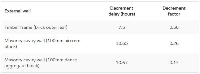
Source: The Concrete Centre (calculated according to EN ISO 13786:2007)
Decrement delay & Thermal buffering, greenspec, [online] Available at < http://www.greenspec.co.uk/building-design/decrement-delay/> [Accessed May 2016]