
Crest Diary Entry No.6 - SIPS Panel Construction
Since the last Article, the construction of the Glulam frame and the thermal blocks has been completed and the erection of the SIPS panels is well under way.

The last couple of weeks have seen the installation of the majority of the SIPS panels. We have decided to use this diary entry to address how we’ve dealt with erection of the SIPS panels and the first steps to achieving air tightness. In the next entry we will discuss the window and door units.
We should probably at this point explain that to achieve passive house standard, the construction does not necessarily have to be designed using timber frame. It can also work as effectively using block work, just like traditional building methods. Although the potential downside of cavity wall construction is that it relies heavily on wet plaster to act as the air tightness barrier on walls and junctions with doors, windows, floors and the roof. Whereas timber frame construction can be lined with vapour barriers and air tightness tapes etc. A cavity wall passive house structure will demand greater attention to air tightness detailing in order to be successful.
Achieving air tightness and minimal thermal bridging becomes a greater challenge when we have to address openings within the building envelope. We modelled various permutations in house using our Passive House Planning Package software at design stage. This has enabled us to address issues of insulation, air tightness and thermal bridging. Translating these exact specifications and performance levels onto site is another challenge.
Super insulation is obviously fundamental to Passivhaus construction. The CREST centre will have 225mm SIP panel (Structural Insulated Panels) walls and roof (Below left image), and 200mm of high-performing insulation in the floor. The SIP panels are constructed from two layers of 12.5mm OSB board with 200mm insulation between. The junctions of these elements are of particular importance to prevent any heat loss.


The SIPS panels came on site with wall openings pre formed ready for the installation of window and doors units at a later date (above right image). The window and door units will then be fixed to this timber frame.
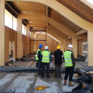
All of the timber walls in the building are constructed on top of thermal block sub walls, with perimeter insulation around the inside of the external walls to help eliminate cold bridging. The connections between the SIPS panel are formed using expanding glue and screw fixings to ensure a thermally continuous joint. A 20mm shadow gap has been left between the vertical Glulam columns in the main demonstration area to allow the timber structure to be expressed as a structural element separate to the walls. In the ceiling there is a 200mm service void left for air ducts and wiring to be installed (below left). A 20mm shadow gap has been left between the vertical Glulam columns in the main demonstration area to allow the timber structure to be expressed as an element separate to the walls.


The image above (right) shows the curved Glulam structure and some of the SIPS panels installed, the air tightness tape can be seen fixed to the top of the timber purlins ready for the installation of the next SIPS panels.
All the junctions between the Glulam frame and the SIPS panels were taped using airtight foil type adhesive tape to ensure air tightness is maintained. This overcomes any differential movement between different materials which may be problematic for achieving air tightness. The images below show the black air tightness tape between the SIPS panels and the Glulam structure.

To compliment the curve of the Glulam beams, faceted acoustic plasterboard will be used create the ceiling of the main demonstration hall. The curve of the Glulam beams will remain visible below the level of the suspended ceiling, allowing them to be expressed in the room along with the Glulam columns of the walls.The next diary entry will address the specifics of the window and door units and how to avoid thermal bridging. The performance of the units themselves, not just the installation, is crucial for meeting the required performance levels.